Are you looking to remotely control the electronic devices in your upcoming project, and want to learn how to program esp8266 WiFi module in order to do so?
Or, do you want to collect and analyze the sensory data of a remote environment, and looking to interface esp8266 WiFi module within that environment?
If, by any means, you intend to use esp8266 wifi module to inculcate the power of internet in your project, you should learn how to program it effectively.
The tricky part is; you don’t need to be an expert in the field of IoT to play around with esp8266.
If you have ever programmed an Arduino, you just need an initial push to get started with esp8266 programming.
Even, if you have not worked with Arduino before, and only a know a little bit about C/C++ programming, you are well versed to ace the programming of esp8266.
Anyways… First things First…
Before we dive into esp8266 programming, you need to know about the different features and specs of esp8266 wifi module, which makes it stand out from the other microcontrollers.
In this tutorial, I will be using a development kit to program esp8266 wifi module which goes by the name of NodeMCU 12E.
This approach will help you avoid the hassle of putting together different components with esp8266 module before you are even able to program it.
So, let’s first explore everything about ESP8266 wifi module…
Article Contents
ESP8266 Microcontroller
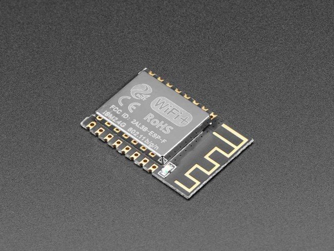
ESP8266 is a wifi-module developed by Espressif systems. It is a self-contained System-On-Chip (SOC) which you connect to the internet and operate it just like any other microcontroller.
ESP8266 contains an on-board WiFi chip which lets you connect it to any WiFi network. Besides, you can interface ESP8266-Wifi module with any microcontroller, and enable them access the internet.
Its distinctive ability is the low-price at which it is available while featuring all the powerful specs. It is specially engineered for Mobile Devices, Wearable Electronics, IoT, and Home Automation Applications.

Powered by Tensilica L106 32-bit RISC Processor, it can achieve extra low-power consumption and a maximum clock speed of 160MHz.
Its power saving architecture allows three modes of operation: active mode, sleep mode, and deep-sleep mode. Low-Power consumption allows it to operate on battery modules for longer periods of time.
ESP8266 Module Versions
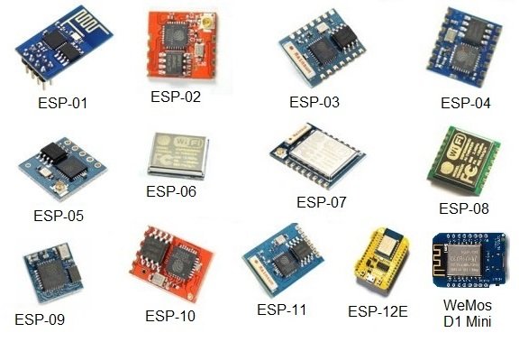
ESP8266 WiFi modules come in different versions as per the demand of the application. The main difference is the number of GPIOs offered in each version.

Till Date, ESP8266-12E NodeMCU is currently the most practical version as it contains a lot of GPIOs. It comes in a completely packaged form, and also contains an in-built FTDI Programmer. All you need is a simple USB cable to program the NodeMCU ESP8266-12E module.
How exciting, right?
Speaking of programming esp8266, lets explore different ways to program this wifi module…
ESP8266 Programming
To program any ESP8266 module, you will need to perform two things:
- Selecting a suitable ESP8266 Firmware
- Uploading the Firmware to flash memory of ESP8266 Module
ESP8266 Firmware
ESP8266 Wifi modules can be loaded with different firmware. In simple terms, each firmware provides a different way to manipulate the Inputs/Outputs of the module.
Even you can write your own, but you won’t be able to get the community support for it. Right?
Some of the standard community-supported firmware for ESP8266 are:
- AT Firmware (AT Commands)
- NodeMCU (Lua)
- Arduino IDE (C/C++)
- Micropython (Pyhton)
In this article, I will explain the steps to program the esp8266 using Arduino IDE.
Uploading Firmware
All ESP8266 modules provide a UART interface to upload the firmware into the flash memory.
If you are using stand-alone modules such as ESP-01 or WeMos D1 mini, you need to use a FTDI (USB Serial to UART) programmer with the UART interface of the ESP8266 modules to upload the firmware as well as program into their memory. You can follow along this tutorial if you intend to do so.
However, NodeMCU ESP8266-12E comes packaged with an in-built CP2102 USB to UART converter to program its flash memory. Thus, you can avoid the hassle of the additional circuitry in case of ESP-12E Dev kit.
ESP8266 GPIO Pins are not 5V Tolerant. Use the FTDI programmer to output the 3.3V instead of 5V. You may also want to power the ESP8266 module with an externally regulated supply of 3.3V, because it can draw a maximum current of 800mA when using WiFi.
NodeMCU ESP8266
NodeMCU ESP8266 Development Kit is based on ESP-12E wifi module. It includes an onboard FTDI serial programmer, and a 3.3V regulator to power the ESP-12E module.
It is a sort of plug-and-play module. Just plug-in a USB cable, program the wifi module, and you are good to go.

Before we move onto programming this module, let’s go through some of the features this development kit offers.
ESP8266-12E NodeMCU Pinout

NodeMCU ESP8266 Datasheet
- Microcontroller: Tensilica 32-bit RISC CPU Xtensa LX106
- Operating Voltage: 3.3V
- Input Voltage: 7-12V
- Digital I/O Pins (DIO): 16
- Analog Input Pins (ADC): 1
- UARTs: 1
- SPIs: 1
- I2Cs: 1
- Flash Memory: 4 MB
- SRAM: 64 KB
- Clock Speed: 80 MHz
- USB-TTL based on CP2102 is included onboard, Enabling Plug n Play
- PCB Antenna
- Small Sized module to fit smartly inside your IoT projects
- Wi-Fi: Built-in 802.11 b/g/n
Now that’s all said and done. Let’s move onto the real programming the NodeMCU ESP8266 board using Arduino IDE.
Material Needed
For this tutorial, we will be flashing the onboard LED of the NodeMCU ESP8266 dev kit. So, let’s gear up:
- A PC/Laptop running Windows/Linux
- USB Type-A to Micro-B Cable
- NodeMCU ESP8266-12E DevKit
ESP8266 with Arduino IDE
Looking at the popularity of the Arduino microcontroller, the simplest and easiest way to program NodeMCU ESP8266 Dev Kit is via Arduino IDE.
Considering the fact that Arduino IDE can be used on both the Windows/Linux, I will explain the steps to program the ESP8266 using both the operating systems.
STEP 1: Install CP2102 Driver
For Windows:
NodeMCU ESP8266-12E module contains an FTDI Serial Programmer. To use this programmer, you need to download and install the CP210x USB to UART Bridge VCP Driver from the official website of SilLabs:

After you have installed the driver, the device should appear in the device manager of your PC:

If the USB-to-UART converter appears in Ports (COM and LPT), you are good to go. Else, you need to reinstall the driver before you can move onto the next step.
For Linux:
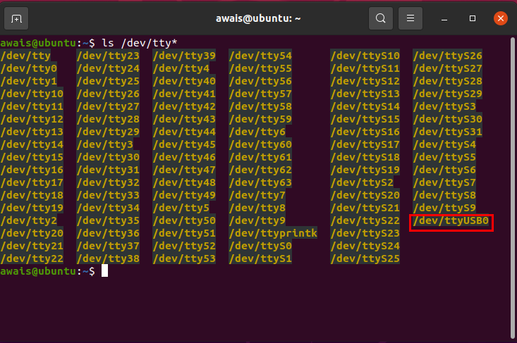
There is no need to install explicit drivers in case of Linux based machine. You just need to check if the serial device is detected or not by running the following command in terminal:
ls /dev/tty*

If the serial device appears in the monitor, you are good to go. Otherwise, reconnect the device so that it is recognized by the linux system.
STEP 2: Install Arduino IDE
For Windows:
Go the official website of Arduino and download the latest stable release of the Arduino IDE for Windows.

Once the download is complete, you need to install the Arduino IDE using the official instructions. Then you should be able to run the Arduino IDE, and use its GUI Interface:
For Linux:
Download the latest version for your Linux System (32-Bit/64-Bit) from the Arduino Website:

After downloading, you need to follow the official instructions to install Arduino on your Linux System.
Don’t forget to add your username to dialout group in order to access the serial port from Arduino IDE:
sudo usermod -a -G dialout <username>
where <username> is your linux user name. You can launch the Arduino by writing the following command in terminal:
arduino
STEP 3: Configure Arduino IDE
For Windows/Linux:
Launch the Arduino IDE. Go to File->Preferences:
Enter the following strings in Additional Boards Manager
http://arduino.esp8266.com/stable/package_esp8266com_index.json
If you have already written the name of some boards, you can separate the URL using a comma.

Advance to Tools->Board->Board Manager. In the search bar, write esp8266 and install the board libraries.

Once the libraries are installed, you need to restart the Arduino IDE for the changes to take place.
STEP 4: Configure NodeMCU Board
For Windows/Linux:
Now you need to select the NodeMCU ESP8266-12E from a range of boards, which can be programmed using the Arduino IDE.
Go to Tools->Board->ESP8266 Boards-> NodeMCU 1.0 (ESP12E Module)
Adjust the Serial port with which the board is attached.
For Windows: You can see the relevant port in the Device Manager->Ports (COM and LPT)

For Linux: Run the command ls /dev/tty*to see the port. If you have only one USB connected, it will mostly be /dev/ttyUSB0

Select the corresponding Serial Port in Tools->Port.

And you are all set to flash your first program in the NodeMCU ESP8266-12E. Let’s do that by flashing the onboard LED.
STEP 5: Flash your First Program
For Windows/Linux:
To flash the first program in ESP-12E, use the already provided examples to evaluate whether the flashing works correctly or not. Later, you can modify the programs as per your liking.
Go to File->Examples->Esp8266->Blink

Compile the program to see if there are any errors. Then upload the program, and make sure the program is uploaded fully into the flash.

If there happens to be no error, you should see the Onboard LED blinking after each second.
Congratulations… You have successfully programmed the flash memory of NodeMCU ESP8266-12E Development Kit. Most importantly, you have explored an avenue to dive into the field of IoT.
Now you need to play around with the board itself. Try to run some more examples and see if you can make them work or not.
In the next articles, I will share more advance tutorials to help you better understand the power of this self-contained SOC.
I have an assignment for you now. Visit the comments section and let me know which sort of articles you will like to read in the future? This will help me write just the articles you need in order to advance your professional career.
Don’t forget to share the article with your friends and colleageus…

He is the owner and founder of Embedded Robotics and a health based start-up called Nema Loss. He is very enthusiastic and passionate about Business Development, Fitness, and Technology. Read more about his struggles, and how he went from being called a Weak Electrical Engineer to founder of Embedded Robotics.

I have tryed to get CP210x USB to UART Bridge VCP Driver to show up in the divece manger. But after many trys no luck. I’m using a windows 10 computer with a HiLetgo ESP8266 NodeMCU CP2102 ESP-12E Development Board.